Ask Lemmy
A Fediverse community for open-ended, thought provoking questions
Rules: (interactive)
1) Be nice and; have fun
Doxxing, trolling, sealioning, racism, and toxicity are not welcomed in AskLemmy. Remember what your mother said: if you can't say something nice, don't say anything at all. In addition, the site-wide Lemmy.world terms of service also apply here. Please familiarize yourself with them
2) All posts must end with a '?'
This is sort of like Jeopardy. Please phrase all post titles in the form of a proper question ending with ?
3) No spam
Please do not flood the community with nonsense. Actual suspected spammers will be banned on site. No astroturfing.
4) NSFW is okay, within reason
Just remember to tag posts with either a content warning or a [NSFW] tag. Overtly sexual posts are not allowed, please direct them to either !asklemmyafterdark@lemmy.world or !asklemmynsfw@lemmynsfw.com.
NSFW comments should be restricted to posts tagged [NSFW].
5) This is not a support community.
It is not a place for 'how do I?', type questions.
If you have any questions regarding the site itself or would like to report a community, please direct them to Lemmy.world Support or email info@lemmy.world. For other questions check our partnered communities list, or use the search function.
6) No US Politics.
Please don't post about current US Politics. If you need to do this, try !politicaldiscussion@lemmy.world or !askusa@discuss.online
Reminder: The terms of service apply here too.
Partnered Communities:
Logo design credit goes to: tubbadu
view the rest of the comments


A scanner would be your best bet.
But you could go wild and ditch the photo idea.
The original piece was modeled in CAD. Simply follow the logical path for how it was originally done.
Measure the outermost dimensions and draw a rectangle as construction geometry. Then play around drawing a couple of circles - chances are that the top and bottom curves are circles and are trimmed and joined with eachother with say blend curve to preserve tangency.
Also measure the distance of the holes to the rest of the geometry. How far are they from the top and sides. You could measure their distance to eachother crosswise too to narrow down the measurement error.
The geometry is built around simple measurements, if you can work out the sketch tools and constraints, you can probably match the original with high precision.
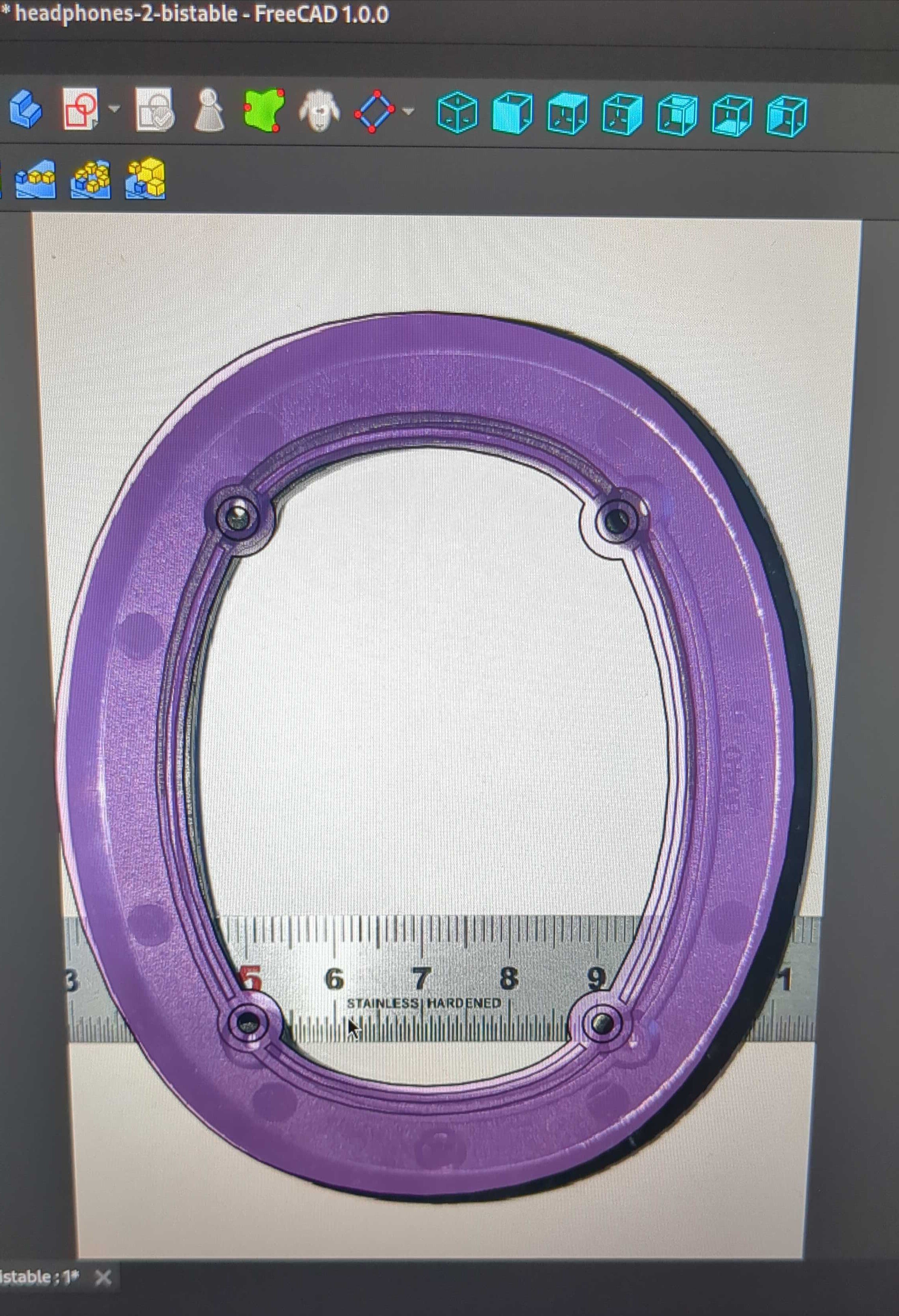
That is what the purple overlay is already. However there are multiple ellipses that are not the same and very minor variation is important. The original part was likely made using surfacing workflow and not a parametric sketch type workflow. The error really needs to be ±0.05 or better, thus the reason it is worth chasing the picture based reverse engineering.
Are you sure the part is as complex as you say? It just looks like lense distortion to me. You can't get an accurate copy from a simple photo. You need special equipment to capture the true proportions