this post was submitted on 13 Sep 2026
15 points (100.0% liked)

Amateur Radio

2828 readers
2 users here now

General amateur radio (ham radio) chat, questions, and news

founded 3 years ago
MODERATORS
 

The Extra exam asks:

E5D10 - As a conductor’s diameter increases, what is the effect on its electrical length?

HamStudy has this explanation:

From the ARRL Antenna book:

the electrical length of a linear circuit such as an antenna wire is not necessarily the same as its physical length in wavelengths or fractions of a wavelength. Rather, the electrical length is measured by the time taken for the completion of a specified phenomenon.

As the diameter increases the resistance decreases, which in effect lengthens the effective "electrical length" of the wire. Thus you could have two wires of differing physical length which are both electrically e.g. "12 wavelength" at the same frequency because the shorter one has a larger diameter.

So, to restate again: the electrical length increases as the diameter increases.

OpenHamPrep explains with (sorry, seems to block copying text):
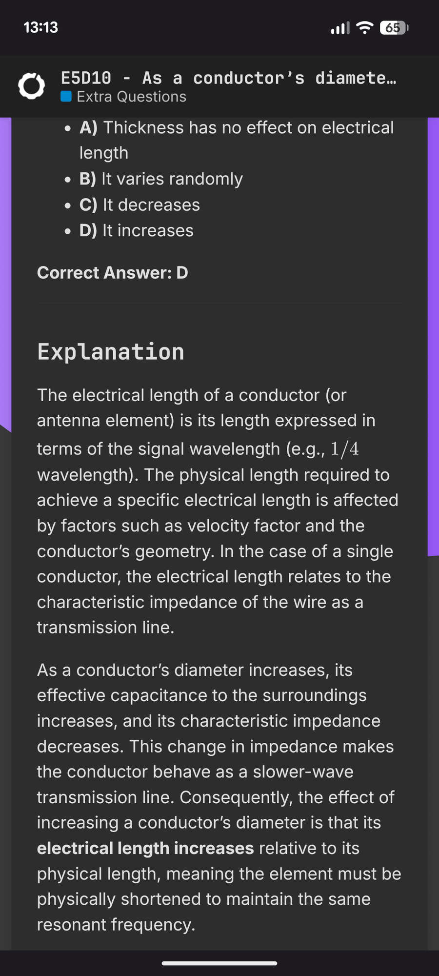
explanation text

I'm having trouble internalizing the explanations though.

Electrical length: How does this relate to velocity factor? I'm picturing how one wavelength at a given frequency fits in the conductor. Compared to velocity factor of 1 (speed of light in a vacuum), if the wire had VF 0.8, I'm picturing that the wave in the wire would oscillate at the same rate but not get as far, so the wave would complete in a shorter physical distance. This matches an equation from picwire:
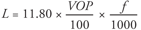
L = 11.8 * f/1000 * VOP/100

From HamStudy's explanation, how would decreased resistance mean increased electrical length?

OpenHamPrep seems to make more sense (bigger diameter = more capacitance). But why does that reduce characteristic impedence, and why would lower impedence mean "slower wave"?

top 6 comments
sorted by: hot top controversial new old
[–] fullsquare@awful.systems 2 points 1 week ago* (last edited 7 hours ago) (1 children)

openhamprep explanation is wrong

When you consider a segment of wire, it has some inductance and capacitance in that small segment, and the wider it is, the lower inductance and higher capacitance are. In other words, both X_L and X_C go down as diameter increases. Electric field lines within antenna are mostly perpendicular to wire everywhere except on ends, where they spread in all directions, which means that there's some residual capacitance there that needs to be charged each cycle. This is called end effect and the wider wire is, the more of it you get. In fact, the same aspect ratio (length/diameter) gets you the same end effect ratio each time, and it's usually in range of 0.98-0.95. If there's insulation, then insulation has lower velocity of propagation as it has higher permittivity than air, and it is in place with highest electric field intensity, and this can also shorten necessary wire length a couple %. The more insulation there is, the more shortened antenna becomes. have a calculator: https://www.translatorscafe.com/unit-converter/en-US/calculator/dipole-antenna/

But wait, there's more. We can think of antenna as a lossy RLC resonator (sort of), where R is Rrad which for halfwave dipole would be 72 ohms, + loss resistance which is smaller, and neither are changing fast with frequency. What is changing faster is X_L and X_C, and the wider wire is, the smaller both of them are (X_L = -X_C at resonance), and this means that you can go further off frequency and still have acceptable SWR, i.e. antenna made with wider wire has more bandwidth, or if we look at it as resonator, lower Q. For HF this means using masts or wire cages instead of single wire, but for VHF this gets more practical

Resistive part of antenna impedance near resonance depends on physical antenna length, and if antenna is shortened, then how it was done, but for the range we're here it won't change much. But also it will depend on height above ground, type of soil, antenna geometry and many other things. 72 ohm is in freespace only

~~you can consider antenna wire as a transmission line, but it will need to include ground as the other side of transmission line, and then impedance is dependent on wire diameter to height over ground ratio.~~ it's not very useful except when considering very large and currently uncommon types of antennas (beverage antenna and rhombic antenna, both of which are traveling wave antennas). other than that, transmission line interpretation only works when antenna is very close to ground in wavelength terms, and usually it's way below what you need for radiation to work properly. when it's way up there, or in free space, there's another impedance that is specific to wire in free space only and not dependent on length, but it's not very useful for explanation of anything in antennas

[–] pageflight@piefed.social 2 points 12 hours ago (1 children)

Thanks for all the explanation!

I also ran across a video from Dr. Kathryn Leigh Smith at UNC-Charlotte which describes this incidentally as part of explaining how dipoles work, and has some nice illustrations. (Current rabbit hole: Should a HB9CV's boom be conductive and electrically bonded to its elements?)

Anyway, got my Extra upgrade!

[–] fullsquare@awful.systems 1 points 7 hours ago* (last edited 3 hours ago) (1 children)

(Current rabbit hole: Should a HB9CV’s boom be conductive and electrically bonded to its elements?)

Yes it has to be, that's how you feed its two elements. Boom is at zero electrical potential and forms half of transmission line that goes to gamma matches of both parts of antenna, and you can attach it to perpendicular conductive mast, or extend it for mounting to mast (has to be perpendicular if mast is metal)

Personally, i'd go with 4el yagi if we're talking portable operation, because boom length is such that you can make it out of plastic tube and hide elements in it when moving around. Or moxon, if size of 4el yagi is prohibitive. Moxon gets you 2db more gain than HB9CV in similar footprint

[–] pageflight@piefed.social 1 points 1 hour ago (1 children)

I hadn't heard of Moxon, I'll check that out. I have an Arrow Yagi, so I'm mostly just playing around to see what I can build, but also thinking of something that's a little easier/shorter to carry around for a fox hunt.

Thanks!

[–] fullsquare@awful.systems 1 points 55 minutes ago

Moxon is very slightly shortened 2el yagi. That other thing is effectively weird phased array of two almost halfwave dipoles, and it's both worse and bigger, and also harder to make because it requires capacitors for gamma match

[–] BCsven@lemmy.ca 1 points 1 week ago

I guess you could think of it like blowing across a large bottle you get a deep resonance, and blowing across a skinny tube you get a higher pitched tone due to the wave change.

So on a large one, in wires, you compensate the length to adjust the "tone"